

 فارسی
فارسیSome engineers have difficulties properly designing sheet metal parts for manufacturing. That’s not you, of course (wink-wink). Still, we notice that there are certain issues that frequently appear in models that we’ve been
asked to quote. With these issues in mind, we offer this list. It isn’t exhaustive, but strap yourself in and see what many of your colleagues do wrong when they design for sheet metal and submit an RFQ.
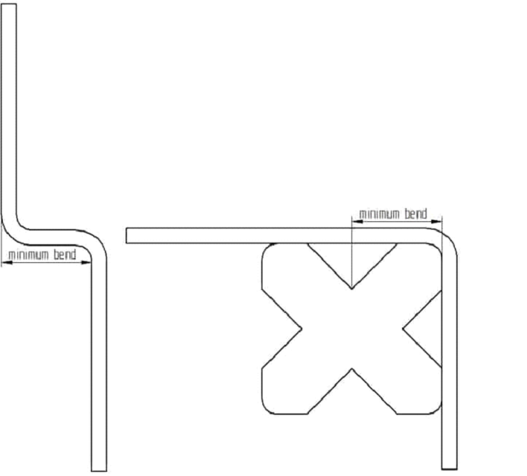
Minimum Flange Length
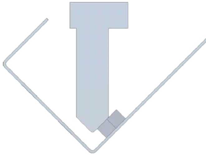
There exists a minimum flange length, as stated already before. See the bending force chart for guidance. According to thickness, the die width is selected. If you design a flange that is too short, it will “fall” awkwardly
into the crevice and you won’t get the result you’re looking for.
Chamfered Sides
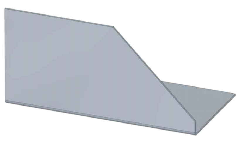
The chamfer must stop before the base of the detail. If you want to make a flange that has one or two ends chamfered, the previous rule of a minimum flange length still applies. The chamfers have to leave enough room to accomplish proper bends, otherwise it will just look deformed and nobody’s really satisfied.
Hole Distance from Bend
Close-by holes may get warped. If the holes are too close to the bend, they may get deformed. Round holes are not as problematic as other types but your bolts may still not fit through. Again, see the bending force chart for minimum flange measurements and put the holes farther than the minimum.
Symmetry
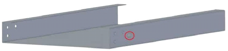
To avoid confusion, the rectangular hole could be on both sides. There lies a great danger in making parts that are almost symmetric. If possible, make it
symmetric. If it is nearly symmetric, the bending press operator may get confused. The result? Your part will be bent in the wrong direction. The symmetry cannot be guaranteed in every instance, but then make sure that
it is easily understood how the manufacturing should be done.
Rivet Nuts
Rivet nut in the way of bending tools. If you use rivet nuts near the bending line, it’s known that inserting them before bending is good for securing the
applicability of it. After bending, the holes may be deformed. Still, make sure that the nuts won’t be in the way of tools when bending.
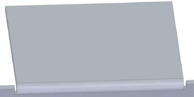
Small Flanges on Big Parts
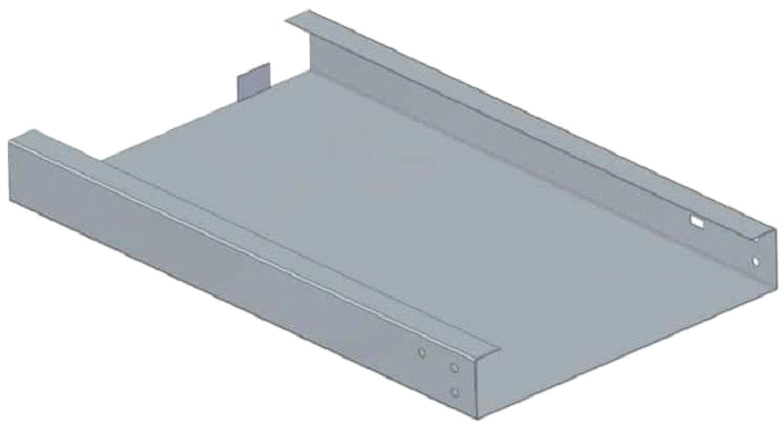
A small bend at the end of a large part may lead to difficulties. It is better to omit small flanges with big and heavy parts. It makes manufacturing very difficult and manual labour may be needed. But it costs more than
simple machining. As a result, it is wiser to opt for alternative solution, if possible.
Bends Next to Each Other
Check the bending force chart for minimum flange length. If you want to include successive bends, check if it’s feasible. A problem arises when you cannot fit the already-bent part onto the die. If your bends face the same direction – a U-bend -, then a common rule is to make design the intermediate part as longer than the flanges.
Keep the Bends on the Same Line
It is best to keep the bends on the same line in case you have several flanges in succession. With this in mind, you can keep the number of operations at minimum.
Otherwise, the operator needs to readjust the parts for every single bend, which means more time and more money.
The Bending Line is Parallel to a Side
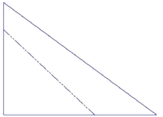
As the headline says. There has to be a parallel side to your bending line for positioning purposes. If not, aligning the part is a real headache and you may end up with an unsatisfactory result.
Bend Relief
To get the best outcome, it is advisable to not only make a small laser cut incision but an actual cutout on the sides of the flange-to-be – a bend relief. The width of such a cut should be above material thickness. This ensures that there are no tears or deformations to the final bend. Another good practice here is to include small radii to the bend reliefs, as they also relieve
material stress.
Bending a Box
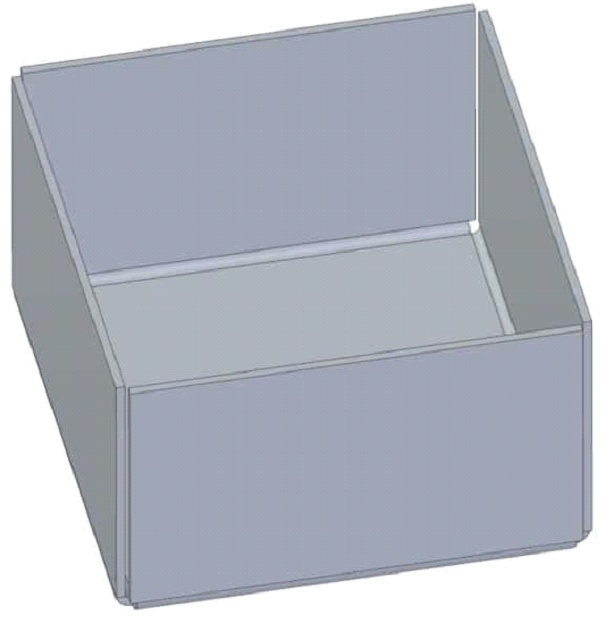
When bending a box, small gaps should be left between the flanges. Otherwise the last bend can crash into the existing ones, breaking the whole structure.
Check the Flat Pattern
One thing to keep in mind is switching your CAD view to flat pattern from time to time. There are many upsides to that. Firstly, if you get carried away with your flanges, you may end up with something that cannot exist in flat
pattern. What cannot exist in flat pattern, cannot exist in any other way.
Measure the layout. Maybe you can adjust the design for optimal fit. Try to avoid going for a bigger sheet if the smaller size is in reach. Maybe you could fit 2 pieces onto the same sheet, if you just shed a few millimetres
off? It will reflect on the final price quotation.
Rule of Thumb for Minimum Bend Radius
Keep it simple. What could be simpler than choosing the inner radius (ir) just the same as the material thickness. This avoids later troubles, overthinking and silly mistakes. Dropping below that value can bring problems your way. Larger radius will just make some other
calculations a little more difficult.
Bending Direction
You should not design your bends in the same direction as the material rolling was done. This is especially important with aluminium and Hardox. Of course, we all know the aluminium casing with 4 sides that means
bending operations contrary to what we are suggesting.
Still, it is better to avoid it if possible. The result can be uneven surfaces or even cracking. Although the manufacturing engineers take care to notice these things, it is good to notice it yourself. It helps to account for material usage.
Consider the Material
The regular thin 1…3 mm structural steel sheets can pretty much take anything. After that, you need to do your research. Some materials are much more capricious about the way they are handled. Getting a
good result depends on your knowledge and on the help your production engineer is able to provide.